ROBOTRONIX WINTER DRIVE
THE IDEA
All of the applications which make our life easier and enjoyable such as Television, Radio, Computers, Mobiles etc. are designed and optimized by new technological growth of electronics and communication systems around us. This field of engineering deals with the electronic devices, circuits, communication equipments like transmitter, receiver, integrated circuits (IC).
Despite the vast potential of growth and excitement, there are several limitations to the current technology which needs to be addressed and optimized for efficient communication and throughput of systems.
Keeping this scope in mind, the RoboTronix team of Flying and Robotics Club underwent a drive the fall of 2019 to reinvent modern solutions from scratch to get a good idea about every aspect of its production.
This drive served as building blocks for laying foundation on advanced understanding of modern devices like cell phones, computers, electric and autonomous vehicles, renewable energy grids, LED lighting, advanced medical devices, and much more. This drive raised the bar of our club's electronics group with new scopes for bigger growth and improvement.
THE PROJECTS
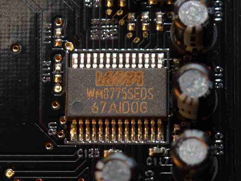
#1 Anologue-to-Digital Converter
In electronics, an analog-to-digital converter (ADC, A/D, or A-to-D) is a system that converts an analog signal, such as a sound picked up by a microphone or light
entering a digital camera, into a digital signal.
Problem Statement
1. Design a 2-bit ADC using the parallel direct conversion method.
2. Implement the design on a breadboard using discrete components.
3. Determine the sampling rate and ideal signal-to-quantization-noise ratio of the ADC.
4. Prepare a brief report on the design and implementation details.
5. (Advanced) Try designing the ADC using a different method/type of your choice.
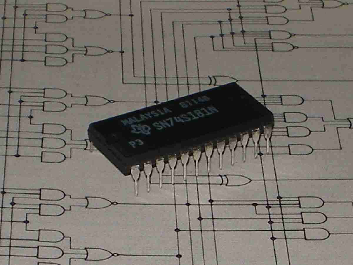
#2 Arithmetic Logic Unit
An arithmetic logic unit (ALU) is a combinational digital electronic circuit that performs arithmetic and bitwise
operations on integer binary numbers. This is in contrast to a floating-point unit (FPU), which operates on floating point numbers.
An ALU is a fundamental building block of many types of computing circuits, including the central processing unit (CPU) of
computers, FPUs, and graphics processing units (GPUs). A single CPU, FPU or GPU may contain multiple ALUs.
Problem Statement
The ALU (Arithmetic Logic Unit) computes one of the following functions on two 16-bit inputs
1. x+y |
2. x-y |
3. y-x |
4. 0 |
5. 1 |
6. -1 |
8. y |
7. x |
9. -x |
10. -y |
11. !x |
12. !y |
13. x+1 |
14. y+1 |
15. x-1 |
16 y-1 |
18. x|y |
17. x&y |
according to 6 input bits denoted zx, nx, zy, ny, f, no.
In addition, the ALU computes two 1-bit outputs:
--> if the ALU output == 0, zr is set to 1; otherwise zr is set to 0;
--> if the ALU output < 0, ng is set to 1; otherwise ng is set to 0.
Implementation: the ALU logic manipulates the x and y inputs and operates on
the resulting values, as follows:
--> if (zx == 1) set x = 0 // 16-bit constant
--> if (nx == 1) set x = !x // bitwise not
--> if (zy == 1) set y = 0 // 16-bit constant
--> if (ny == 1) set y = !y // bitwise not
--> if (f == 1) set out = x + y // integer 2's complement addition
--> if (f == 0) set out = x & y // bitwise and
--> if (no == 1) set out = !out // bitwise not
--> if (out == 0) set zr = 1
--> if (out < 0) set ng = 1
1. Design the ALU in Verilog on Xilinx Vivado without using any conditional or
looping constructs (like if, for, case). Complete up to behavioural simulation
stage, i.e., the first stage in the Vivado workflow.
2. Prepare a brief report on the design details.
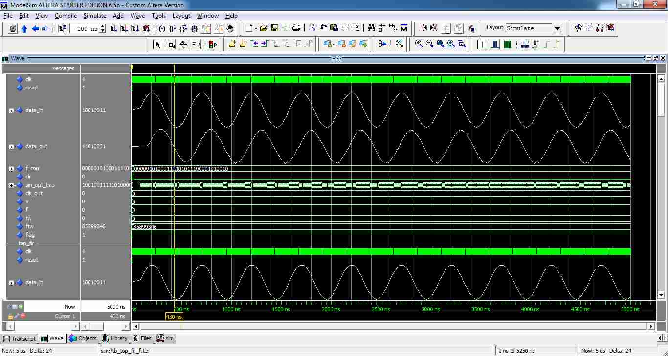
#3 Finite Impulse Response filter
In signal processing, a finite impulse response (FIR) filter is a filter whose impulse
response (or response to any finite length input) is of finite duration, because it
settles to zero in finite time. This is in contrast to infinite impulse response (IIR)
filters, which may have internal feedback and may continue to respond
indefinitely (usually decaying).
Problem Statement
1. Design an 8-tap FIR filter module with Verilog on Xilinx Vivado.
a. Choose the tap values to be anything. This is just to verify the
working.
b. Complete the design till the behavioural simulation stage, i.e, the first
step in the Vivado workflow.
2. Prepare a brief report on the design details.
3. (Advanced) Complete the design till the post-synthesis stage.
#4 Morse Code Encoder & Decoder
Morse code is a character encoding scheme used in telecommunication that
encodes text characters as standardized sequences of two different signal
durations called dots and dashes or dits and dahs. Morse code is named for
Samuel F. B. Morse, an inventor of the telegraph.
Problem Statement
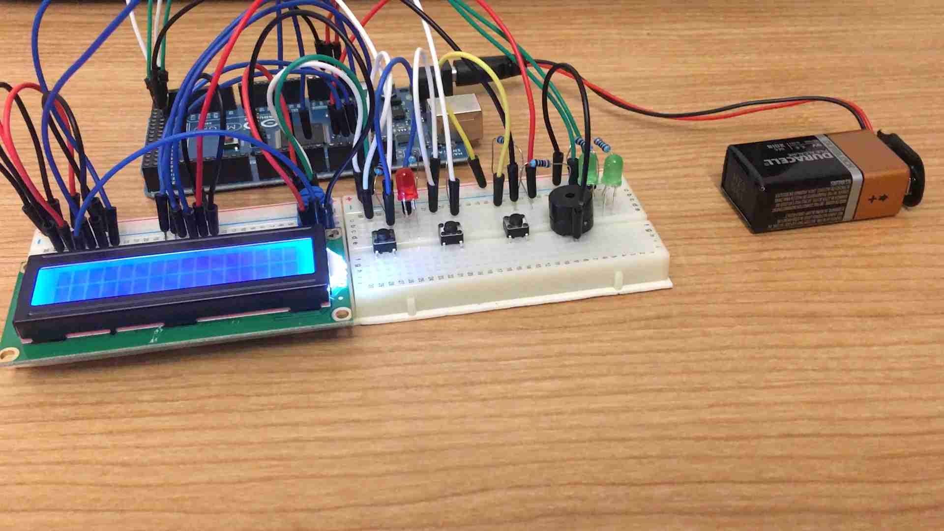
1. Design a Morse code encoder and decoder.
a. You may use any signal for encoding (eg: visible light or an audio signal) so long as you can measure it and reproduce it.
2. Prepare a brief report on the design details.
#5 People Counter
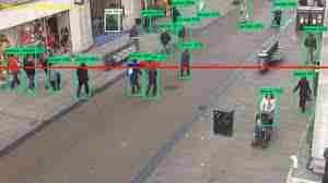
A people counter is an electronic device that is used to measure the number of
people traversing a certain passage or entrance. Examples include simple manual
clickers, infrared beams, thermal imaging systems, WiFi trackers and video
counters using advanced machine learning algorithms. They are commonly used
by retail establishments to judge the effectiveness of marketing campaigns,
building design and layout, and the popularity of particular brands.
Problem Statement
1. Design a people counter.
a. The counters should be installed in at least two locations so try to
create a scalable design and a simple but effective method of
counting people.
b. Have a LED setup in each location that turns off when the people
counter records a 0 and turns on if otherwise.
2. Prepare a brief report on the design details.
3. (Advanced) Create a simple app that indicates the number of people at each
of the locations and allows for a threshold to be set for the LED setup to
turn on. (Example, if the threshold is 5, the LED setup will turn on only if 5
or more people are recorded at the location at that time).
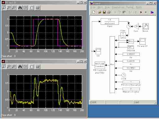
#6 Software PID Controller
A proportional–integral–derivative controller (PID controller or three-term
controller) is a control loop mechanism employing feedback that is widely used in
industrial control systems and a variety of other applications requiring
continuously modulated control. A PID controller continuously calculates an error
value e(t) as the difference between a desired setpoint (SP) and a measured
process variable (PV) and applies a correction based on proportional, integral, and
derivative terms (denoted P, I, and D respectively), hence the name
Problem Statement
1. Design a software PID controller for a DC motor to ensure a steady speed
(fixed rpm). You can omit the differential or integral term as you see fit.
2. Implement the design.
a. You may choose the value of rpm (setpoint)
b. Determine a way to measure the process variable.
c. The process of selecting the constants for the proportional, integral,
and differential terms is trial-and-error.
3. Prepare a brief report on the design and implementation details.
4. (Advanced) Account for integral wind-up in the design and implementation.